
So, things have been rather quiet for a while. I’ve been delving into hardware in a major way. One of the design goals for our home automation system is to get as much as possible of it out of the cloud, and disconnected from the Internet. Rather than Internet of Things (IoT) stuff, we want a local Network of Things.
One advantage of using Lifx lights throughout the house is that they can be controlled remotely without sending instructions to the Lifx Cloud service, and I’ve got them fully connected up to OpenHAB and written a implementation of basic variable-duration scene transitions, allowing me to change light settings as we want them. This was a great start.
Generally, the OpenHAB apps for phones, tablets, and local web browsers are pretty good for controlling the things that haven’t been completely automated or for breaking the regular patterns, but one thing we really needed was a backup physical device that guests can use to adjust things, too.
I’ve noticed these new “Smart Clock” devices creeping into stores, and I quite liked the idea of them, if not the “being tied into a particular automation system” part, so I thought it was time to do something more with a Raspberry Pi than running a simple MQTT broker.
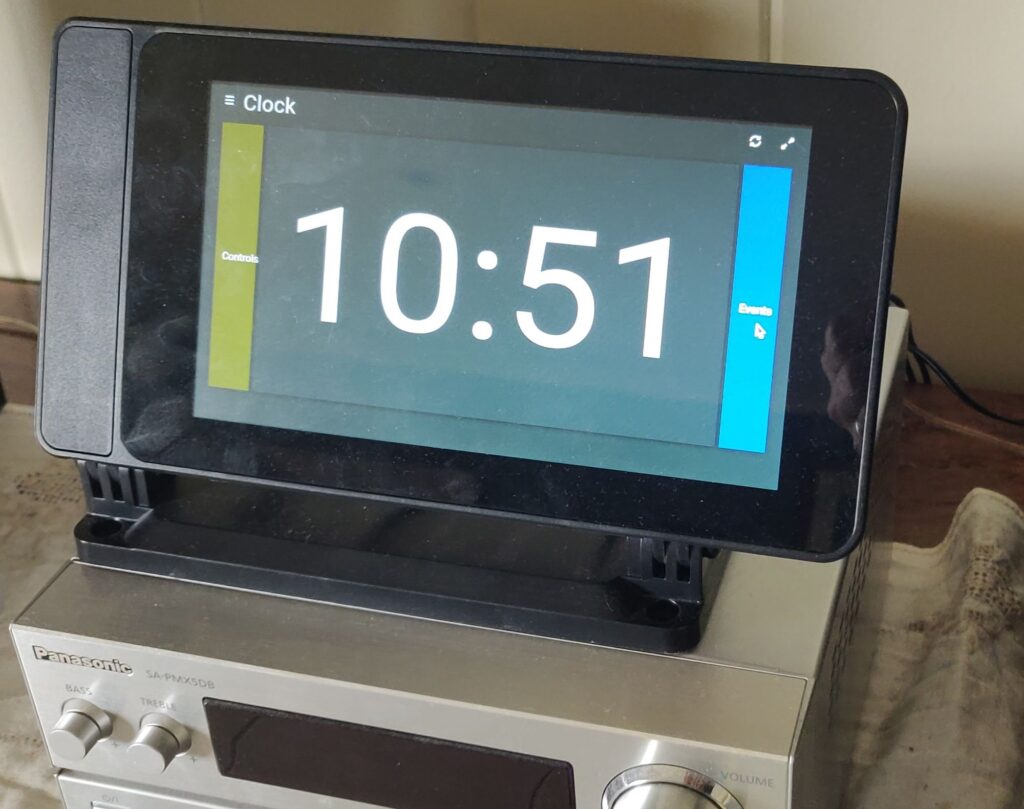
This is a basic Raspbian install, configured to auto-launch Chromium pointed to a specific OpenHAB interface page on my server. Most of the time, it just shows a nice big clock that’s readable from a distance.
There’s also a background service running that queries the OpenHAB server to get an idea about how bright the screen should be. If it’s night time, and we’re all in bed, the screen brightness gets lowered to the absolute minimum so the ambient glow from the lounge doesn’t disturb us when we’re sleeping.
The two buttons on either side of the time lead into the rest of the OpenHAB interface:
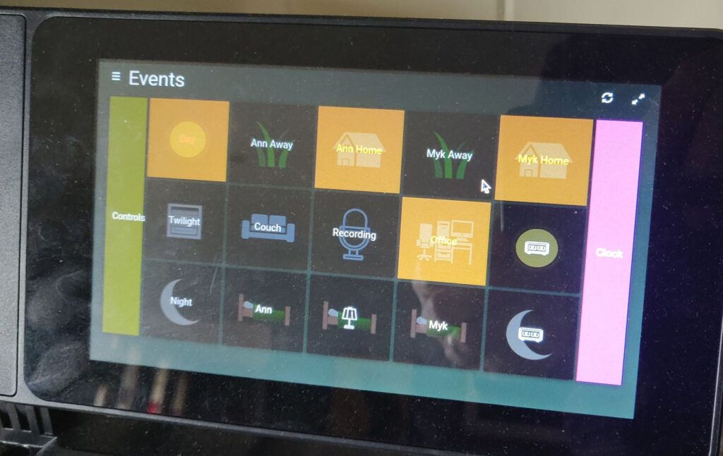
This “Events” page is the main high level controls, letting us tell OpenHAB that we’re home or away, or in a specific location that triggers different rules. The Couch and Office buttons are mainly to tell the system whether our spot heaters should be active. The Recording button shuts off all the noisy appliances (and will one day trigger a sign above the hallway door leading to the recording studio).
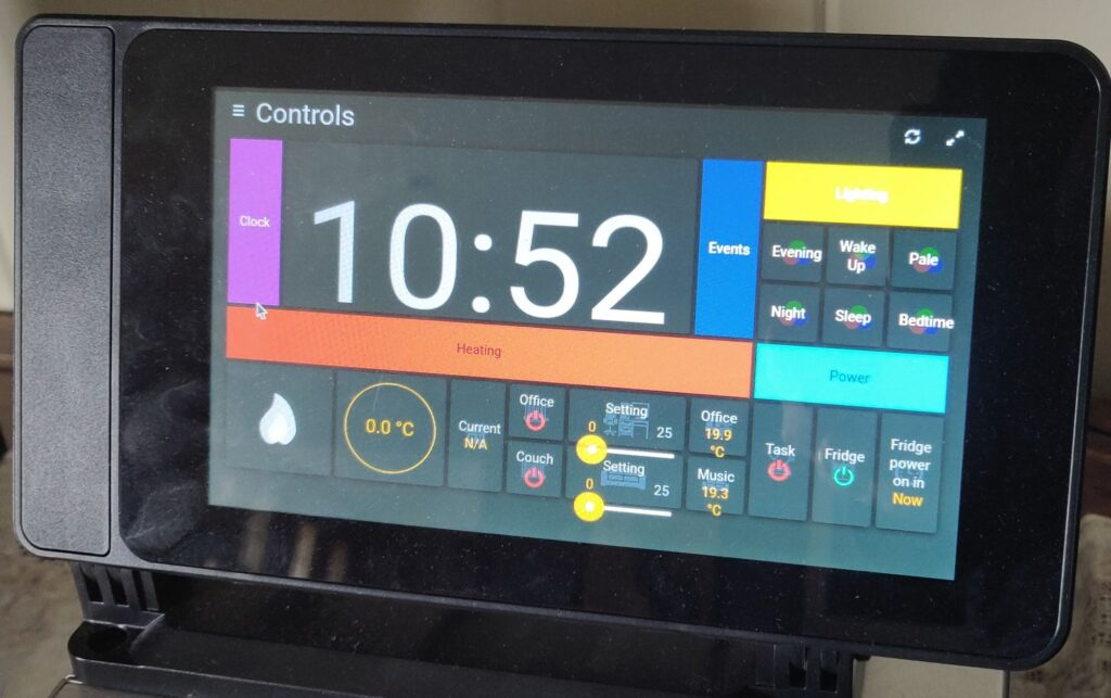
The “Controls” page allows for a little more fine-grained control of specific functions. There’s a few of the most commonly used lighting scenes, controls for the objects running on Wifi Power switches, and thermostat controls for the house heating as well as our two spot heaters. There are a few other screens accessible by hitting various buttons or headings. To be honest, this Smart screen interface is lagging behind the version designed for mobile phone screens, since that’s what we mostly use.
In order to control the house heating, I’ve added a trigger to the heating unit in the roof. The gas heater has a simple stepped-down AC voltage control loop that the wall thermostat simply closes when heating is desired and opens when it is not. Wiring in an additional loop to a Tasmota device was quite simple.
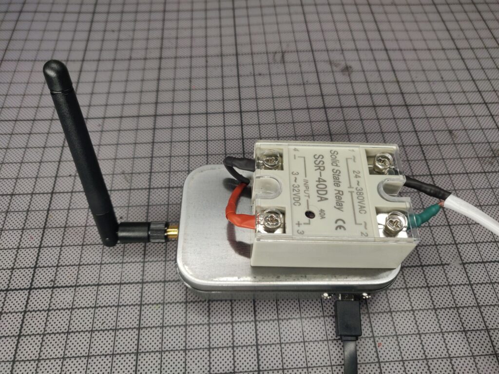
The loop voltage is only 24VAC, so this relay is right at the bottom edge of its working voltage range, and I’m actually finding that it occasionally doesn’t reset cleanly, so I may end up replacing this with a lower rated relay.
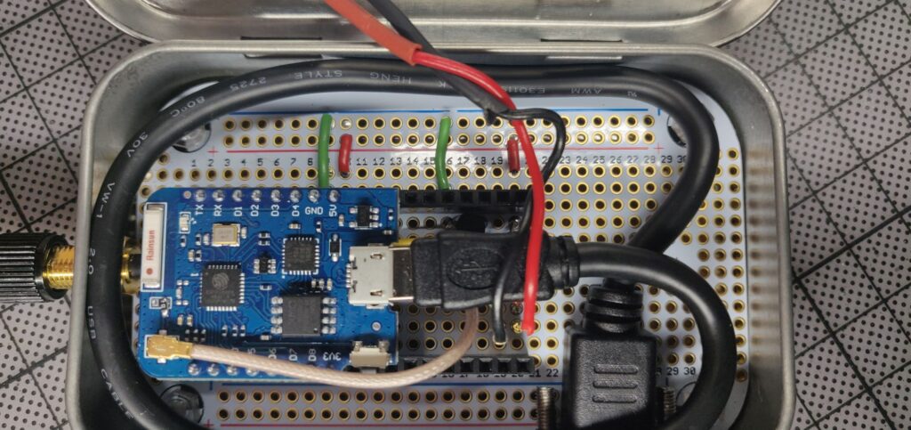
Very simple wiring, just a transistor to replace the 3.3V signal output from the D1 Mini to a full 5V control signal from the USB power input. Metal tin enclosure for robustness in the roof space, which necessitated the use of a separate antenna rather than relying on the surface mounted one.
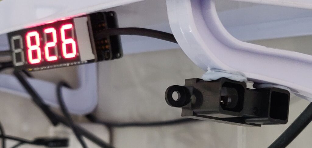
Of course, having a relay to turn the heater on and off is no use if you don’t know what the temperature is! That was another project (which actually preceded the relay)
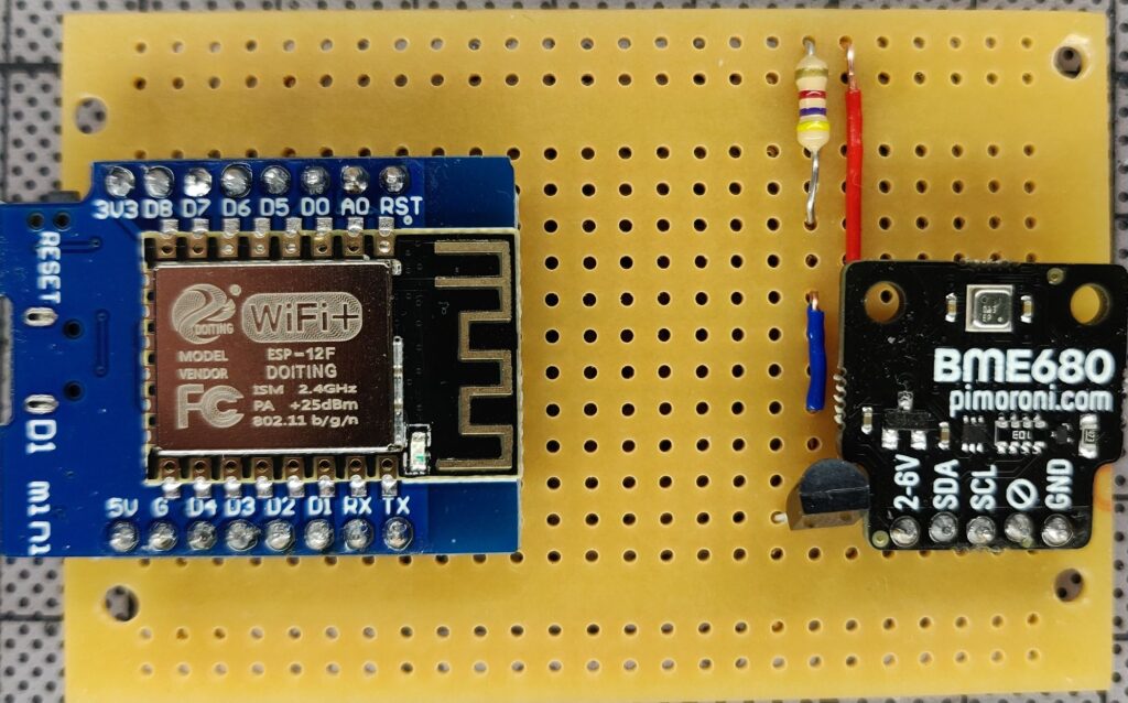
So this was my first go at a thermometer. A proof of concept that all the parts would work together. With the discovery of a super easy PCB design and fabrication service, I ended up with a much cleaner design (you don’t want to see the back of that breadboard!)
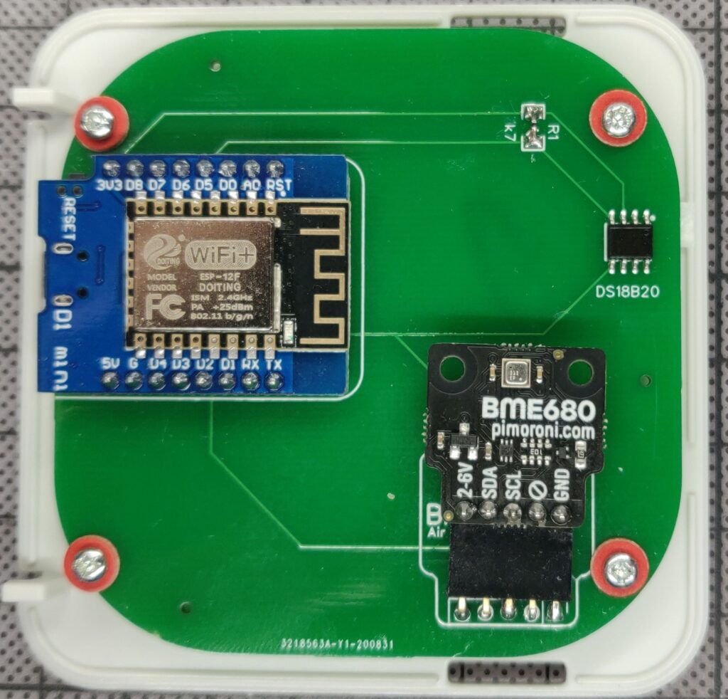
Now, this design has a few issues, it turns out. We’ve determined that the DS18B20 temp sensor is basically not worth using, as it is quite inaccurate compared to the BME680, we are getting some thermal transfer from the microcontroller to the sensors, and the design is not ideal for encouraging airflow. Turning them upside down has improved things a little:
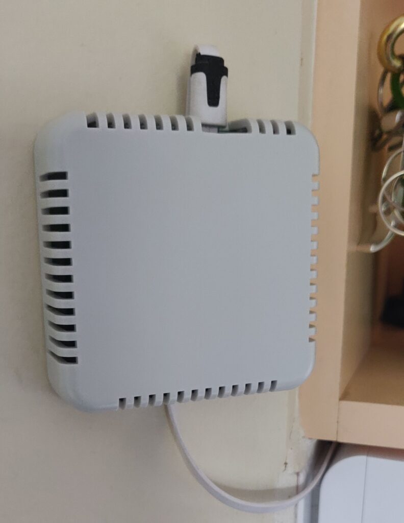
But ultimately, I think I can do better, and I have a design ready to order for a Mk2, which will actually be cheaper thanks to not requiring any surface mount components.
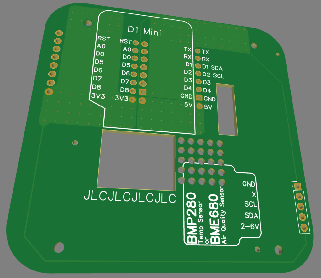
This has a few improvements over the Mk1.
- There’s a bunch of holes to reduce thermal transfer from the D1 Mini microcontroller to the BMP280/BME680 sensors.
- There are some substantial copper areas attached to the 5V, 3V3 and GND pins to hopefully exhaust as much heat as possible from the D1 Mini’s power regulator
- Both the sensors and the D1 Mini are connected via pairs of right angled connectors, so the only components actually soldered to the board are cheap and easily replaceable if a future design revision is required.
- Substantial PCB hole below the D1 Mini allows the plug to be connected inside the enclosure, requiring a smaller hole in the enclosure and looking neater.
- Thermal design should generate some airflow out of the top of the enclosure, pulling fresh air into the bottom for the sensor.
- Secondary pads for all D1 Mini pins for possible additional device connection (for controlling lights, other sensors, etc)
- Corner radii reduced to fill enclosure better
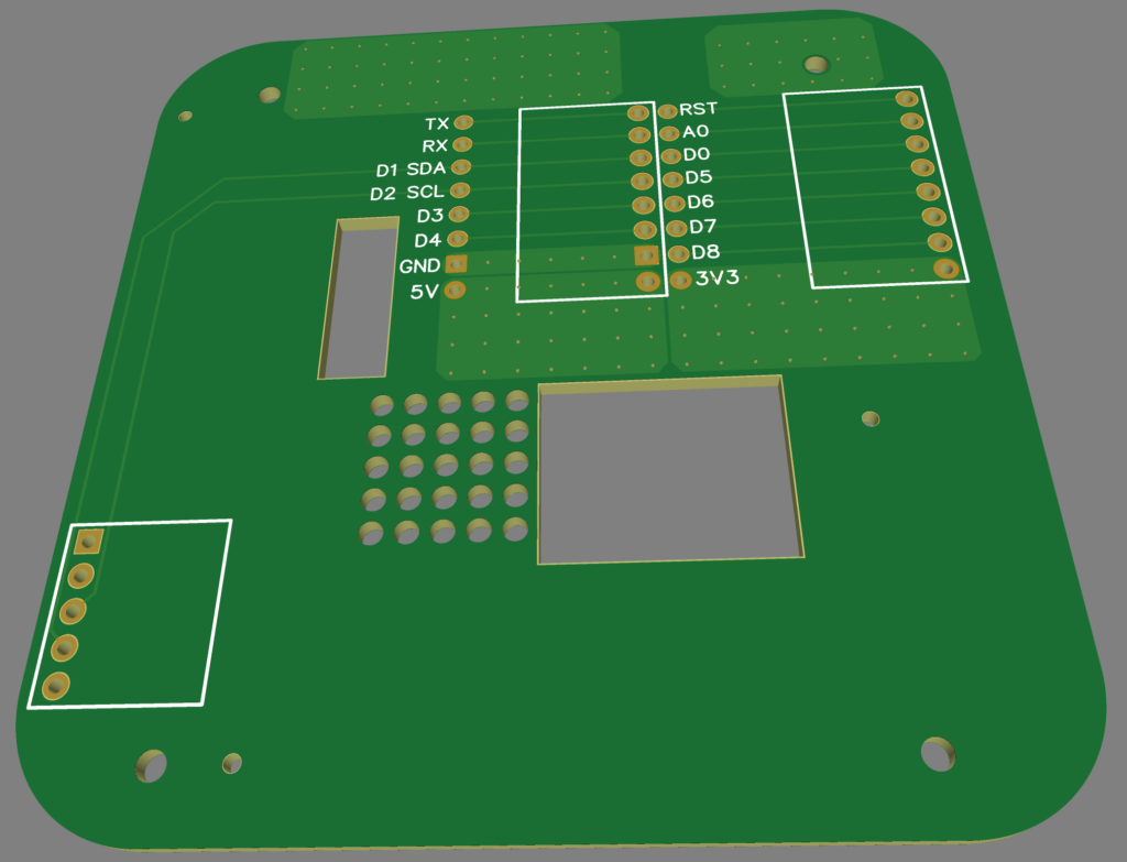
Back of the PCB labels the secondary pads clearly and shows the positioning of the right angled female headers. There are also additional copper areas as part of the thermal design.
I plan to order a batch of these PCBs soon. Using these D1 Minis (or D1 Mini Pro for the relay) makes it super easy to use pre-compiled Tasmota binaries flashed to the microcontroller via USB, after which it’s not all that difficult to configure them to talk via an MQTT broker to OpenHAB.
In the meantime, Tasmota was not the answer for one other project I’ve been working on that has caused many frustrations, which I think I’ll break into a separate post. Here’s a sneak peek: